- Diagram Fasor Rangkaian Rlc
- Cara Menggambar Diagram Fasor Rlc
- Gambar Diagram Fasor Rangkaian Rlc
- Soal Diagram Fasor Rlc

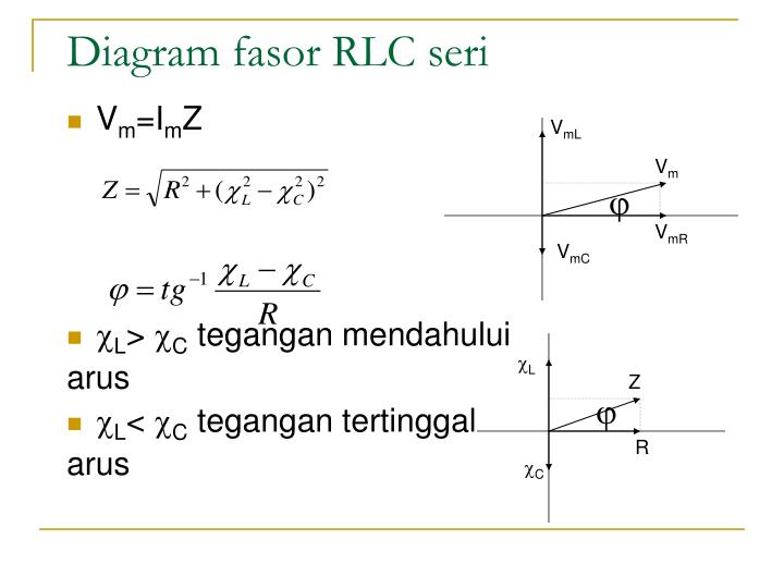
Aa) Diagram fasor arus dan tegangan dari rangkaian RLC di atas bb) Diagram fasor hambatan, reaktansi dan impedansi dari rangkaian RLC di atas NEXT PAGE: 1 2. Diagram fasor rangkaian rlc paralel. Masih banyak lagi contoh dari penerapan rangkaian paralel pada lampu. Baca juga hukum ohm dan contoh soalnya. Pada rangkaian rlc paralel terjadi pembagian arus listrik dari sumber menjadi tiga yaitu menuju ke resistor induktor dan kapasitor.
A series RLC circuit consists of resistance, inductance, and capacitance in series. Whenever we apply a sinusoidal voltage across the series RLC circuit every voltage and current in the circuit will be also sinusoidal in its steady-state condition. The only difference is in its amplitude and phase angle. It is obvious that there will be no change in the frequency of the signals. In other words, the voltages across the resistance inductance and capacitance will have the same frequency as that of the source.
Response of Series RLC Circuit
Dari gambar diagram fasor terlihat bahwa antara tegangan dan arus terdapat beda sudut fase sebesar θ yang dapat dinyatakan dengan: Besarnya arus yang melewati rangkaian RLC adalah sama, sehingga besarnya tegangan pada masing masing komponen R, L, dan C dapat dinyatakan: V R = I R, V L = I X L dan V C = I X C.
We have shown one simple basic series RLC circuit here in the figure.
The source voltage is sinusoidal and we can represent it as
The impedance of the series RLC circuit is

Therefore the current flowing through the circuit is
Now the expression of the impedance of that RLC circuit can be rewritten as
The polar form of this impedance is
Condition of Inductive Circuit
The above-mentioned series RLC circuit shows inductive nature when the inductive reactance is much much more than the capacitive reactance of the circuit.
Condition of Capacitive Circuit
The circuit shows its capacitive nature when the capacitive reactance is much much more than the inductive reactance.
The phase difference between the voltage and current is given by
Whenever the inductive reactance is much higher than the capacitive reactance this angle becomes positive. Therefore we can conclude that the current lags the voltage with this angle.
On the other hand, when the inductive reactance is much less than the capacitive reactance this angle becomes negative. In that case, the current leads the voltage with this angle.
Ultimately we can summarise that in the inductive circuit the current lags the source voltage and in the capacitive circuit the current leads the source voltage.
Phasor Diagram of Series RLC Circuit
Phasor Diagram of Inductive Series RLC Circuit
We normally take the direction of the circuit current as the reference axis of the diagram. The voltage drop across the resistance will have the same phase as that circuit current. The voltage drop across the inductive reactance will be perpendicularly upward on the current axis. This is because the voltage drop across a pure inductance has exactly 90° phase advancement in respect of the current. In other words, the current lags the voltage at exactly 90°. The voltage drop across the capacitive reactance will be perpendicularly downward on the current axis.
Phasor Diagram of Capacitive Series RLC Circuit
In contrast, across the pure capacitive element, the voltage lags the current by exactly 90°. Alternatively, we can say the current leads the voltage by exactly 90°. The resultant voltage across the entire reactive part of the circuit is the difference between inductive and capacitive voltage drops. The vector sum of the resistive voltage drop and reactive voltage drop is the source voltage of the circuit.
If the inductive voltage drop is more than the capacitive voltage drop, the resultant reactive voltage will be perpendicularly upward.
On the other hand, if the capacitive voltage drop is more than the inductor voltage drop, the resultant reactive voltage will be perpendicularly downward.

Resonance in seriesRLC Circuit
When the frequency of the applied alternating source (ωr) is equal to the natural frequency| 1/ √(LC) | of the RLC circuit, the current in the circuit reaches its maximum value. Then the circuit is said to be in electrical resonance. The frequency at which resonance takes place is called resonant frequency.
Resonant angular frequency, ωr= 1/ √(LC)
Diagram Fasor Rangkaian Rlc
Since XL and XC are frequency dependent, the resonance condition (XL=XC) can be achieved by the varying the frequency of the applied voltage.
Effects of series resonance
When series resonance occurs, the impedance of the circuit is minimum and is equal to the resistance of the circuit. As a result of this, the current in the circuit becomes maximum. This is shown in the resonance curve drawn between current and frequency (Figure 4.54).
Cara Menggambar Diagram Fasor Rlc
At resonance, the impedance is
Therefore, the current in the circuit is
The maximum current at series resonance is limited by the resistance of the circuit. For smaller resistance, larger current with sharper curve is obtained and vice versa.
Gambar Diagram Fasor Rangkaian Rlc
Applications of series RLC resonant circuit
Soal Diagram Fasor Rlc
RLC circuits have many applications like filter circuits, oscillators, voltage multipliers etc. An important use of series RLC resonant circuits is in the tuning circuits of radio and TV systems. The signals from many broadcasting stations at different frequencies are available in the air. To receive the signal of a particular station, tuning is done.
The tuning is commonly achieved by varying capacitance of a parallel plate variable capacitor, thereby changing the resonant frequency of the circuit. When resonant frequency is nearly equal to the frequency of the signal of the particular station, the amplitude of the current in the circuit is maximum. Thus the signal of that station alone is received.
